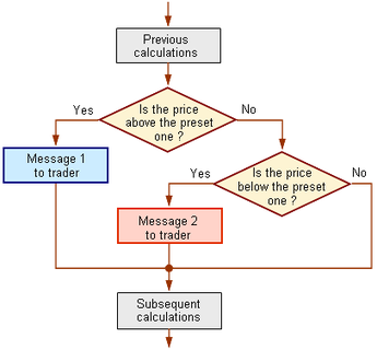
 Now try this one using only the block diagram. Hint : study carefully the nested statements in the quadratic equation problem.
use: double high_preset_value = 35.6; double low_preset_value = 22.5; double price; // the current price Message 1 and 2 should inform the trader whether he is under or above the preset prices. 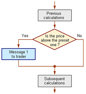 IB expects from you to be able to construct an algorithm from a block diagram. In this first problem the block diagram and the "statement of the problem" are given to make your task easier.
Problem: construct an algorithm - only the specific part of the block diagram, no need for a whole program. Compose a program where the following conditions are realized: If the price (double price, is the data you enter) for a symbol has grown and exceeded a certain value (25.67 is the preset value ) , the program must inform the trader about it (output message using a System.out.println(....)); if it hasn't exceeded this value, the program mustn't perform any actions. Modulo arithmetic has to do with "special" division between integers. Modulo arithmetic is often used as a hashing function to generate a key to be used as address location for storage of data into Tables, Files and Memory. The same method can be used to retrieve data.
Can you state which kind of Primitive Data declarations are suitable for Modulo Arithmetic in Java? Example 25 DIV 9 = 2 result integer (gives how many times 9 can divide 25) 25 MOD 9 = 7 result integer (gives the remainder of the divisiion) example Java course code for the above (but not the only one, why? ) int d,m; d = 25 / 9; m = 25 % 9; Read Liang book with the program for the milliseconds, and then try to complete the ATM (Automatic Teller Machine) exercise 6. 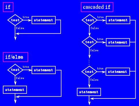 We have constructed different algorithms for decision making such as the "quadratic equation". We have used if, if..else, cascade if.
We can use block diagrams to represent those decision making procedures . Could you design a "cascade if .. else " block diagram? You are expected to:
Read the relevant chapter in your book. For the Higher Level some additional reading click on This is what is expected for Higher Level:
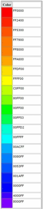 You should be able to calculate how many colors we can represent using the available number of hex digits or binary digits. You must also be able to reason why we prefer to use hex representation over binary.
Here is a summary, for further reading read your book or click here to see more on how we can calculate total number of colors and what is represented by each hex section. Summary: There are many ways of representing an individual color. For a few colors, some commands in Active Worlds support the use of pre-defined color names, but for the rest of them an alternative method is needed. Hexadecimal RGB color values represent the amounts of Red, Green, and Blue light necessary to simulate the color with most standard televisions or computer monitors. Each of the three parts is represented as a two digit hexadecimal value in the range of 00 to FF, so the total hexadecimal RGB range is from 000000 to FFFFFF and includes a total of 16777216 distinct color representations. (1000000 hexadecimal = 16777216 decimal.) This page lists a few of them for you to choose from, to help you get a feel for the process of using hexadecimal RGB color values. Most of the tables listed on this page contain groups of colors based on the pre-defined color names and are provided here with their hexadecimal RGB values for your convenience, for use with action commands such as sign, color, and light. You should be able by now to write Boolean expressions from Logic Gate circuits or construct circuits from Boolean expressions, construct truth tables and prove equality of Boolean expressions using truth tables. Operators to be used are AND, OR, XOR, NOT, NAND, NOR.
1. Click to the link here for your homework Exercises 5 to be delivered on Tuesday 23/10. 2. Here is an introduction for the gates for further reading click here 1 click here 2 click here 3 Summary A logic gate is a circuit which uses digital signals as its inputs and outputs. What makes a circuit a gate is that each output depends entirely on the signals applied at the inputs. If these input signals change, then the output signal may also change. Digital circuits which use logic gates are usually arranged so that a logic 1 appears at an output only for some definite combination of input signals - for this reason these circuits are sometimes called combinational logic circuits. In theory, we could make i.c.s for each and every possible combination of input signals to produce a 1 output, but this would be wasteful of resources. In practice, what is done is to make i.c.s which accomplish a few standard logic operations. From these standard logic i.c.s any combinational logic circuit can be built up. The microprocessor is an extension of this idea - a circuit which can perform virtually any logic function. The action of a standard combinational logic circuit, or of any circuit made up from these units, can be described in two ways.
Boolean algebra, incidentally, was invented long before modern computers. It is named after George Boole (1815-1864) who devised it as a method of turning logical statements into algebraic expressions. Little use was made of this work until Shannon found in 1938 that Boolean algebra could be usied to analyse relay circuits which carried out the sort of switching operations we now refer to as 'AND' and 'OR' gates. We use nested if .. else statements to solve the different choises we have for the solution of the Quadratic equation.
The program is split into modules (called methods in Java). *MODULARITY - ADVANTAGES (reference to computational thinking) *(INSERT METHOD - CALCULATE METHOD - OUPUT METHOD) *1. MODULARITY ADDS TO THE READABILITY OF THE PROGRAM *2. EASIER TO TEST AND DEBUG *3. CODE REUSE - YOU CAN CALL THE SAME METHOD FROM DIFFERENT PARTS OF THE PROGRAM *4. DIFFERENT PARTS OF THE PROGRAM CAN BE DEVELOPPED FROM DIFFERENT PROGRAMERS AT THE SAME TIME - OFCOURSE * THEY MUST AGREE BETWEEN THEM INTO SOME CONVENTIONS LIKE SIZE OF THE MODULES, NAMES OF THE VARIABLES ETC *5. THE PROGRAM IS EASIER TO MAINTAIN AND UPGRADE Try to find an algorithmic solution to the equation at the end of the program. You may wish to consult the books in the library or your prof in Maths. |
AuthorDr.Harris Stroumpos, M.Sc., Ph.D., Archives
January 2013
Categories |
 RSS Feed
